
Pogo Pin Programming Introduction
The Pogo pin programming cable is basically a spring needle that is molded in a handle that connects the programmer to the device to be programmed. They are similar to the full test fixture, but are more flexible because they are not designed specifically for a PCB.
Tag-Connect comes with several different cables that connect various programmers to projects and MCUs. There are three different connector sizes:
- The TC2030 is a 02 x 03 (6 Position) connector,
- The TC2050 is a 02 x 05 (10 Position) connector,
- The TC2070 is a 02 x 07 (14 Position) connector.
 |
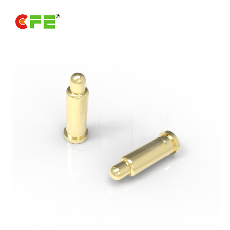 |
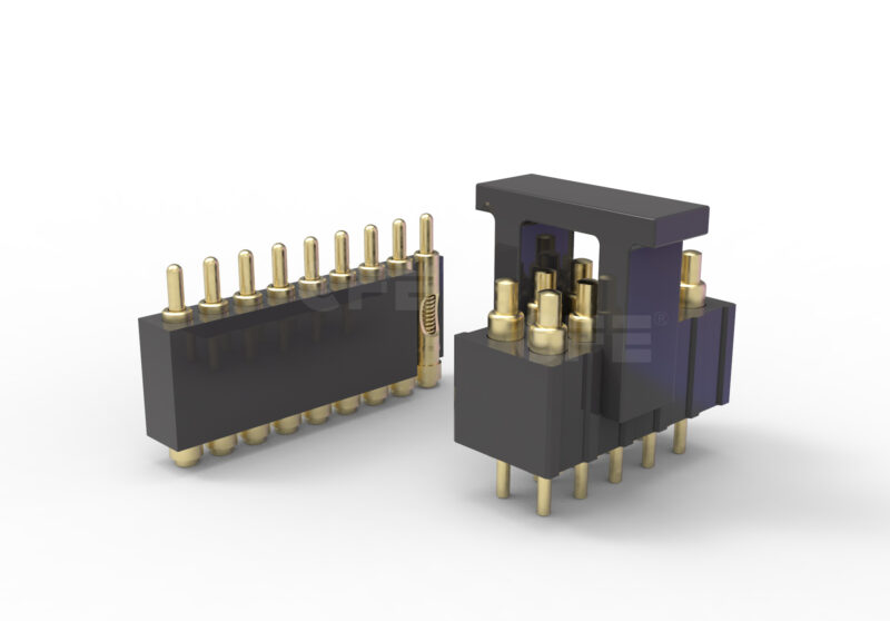
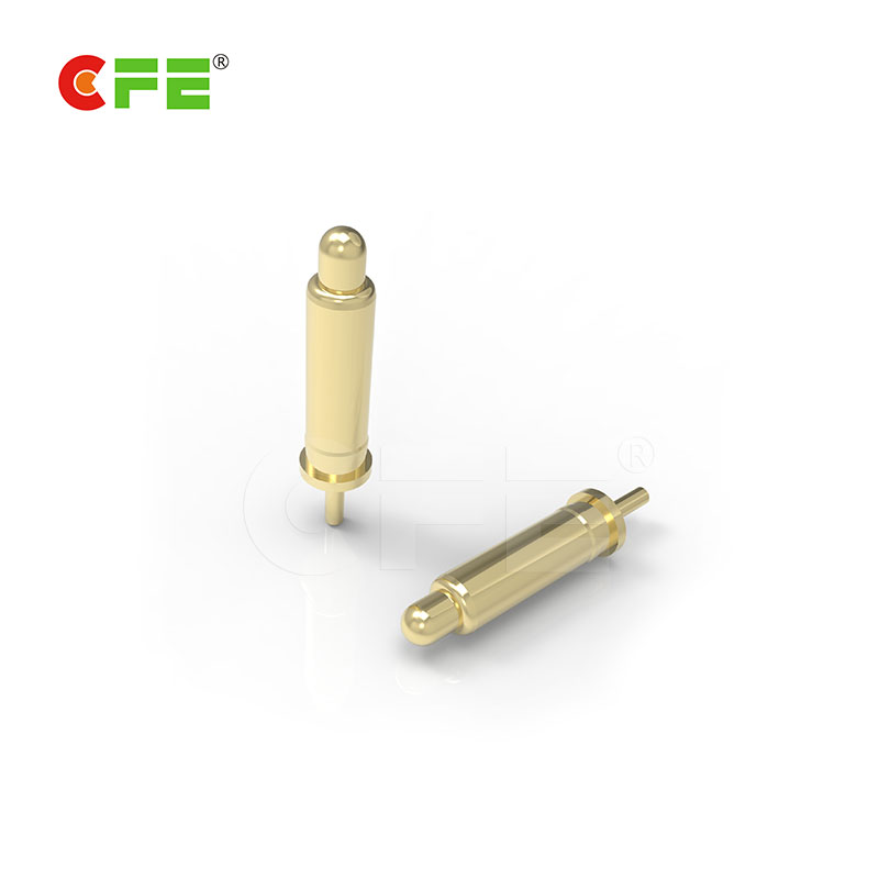
| [MF310-1111] DIP spring loaded pins for pcb testing | [MF200-1111] SMT spring contact pins wholesale |
Here is how Pogo pin programming works
When the socket is made, the top inserter is reversed. Place the probe in each hole. Each hole is “conical”. The probe fits in the hole, but because the bottom of the hole is smaller than the “shoulder” of the probe, it does not fall.
Next, place the spring on the bottom of each probe. Next, the “bottom inserter” (inverted) is located at the top of all springs. The holes in the bottom Pogo pin programming inserter are tapered.
Once the assembly process is complete, an “insert sandwich” is created. The finished Pogo pin programming inserter layer is turned so that the right side upwards (the probe protruding from the top and the spring protruding from the bottom) and positioned into the appropriate “normalized housing”.
Finally, place the “pressure pad” in the “standardized house” cover. Once the completed socket bolts are attached to the test board, the bolted connection will cause the spring-loaded from the bottom of the bottom Pogo pin programming inserter to fit through the “pressure mounting” of the customer test board. The customer places the device in the test socket and closes the lid. The closing of the lid causes each device to cause the top of the corresponding probe to mate with it.
The closure of the lid also causes each spring to “tilt”, resulting in a very short signal path because the signal path is from the device to the probe head to the (tilted) spring to the test pad.


